Problem Statement No. 2011-TN/27
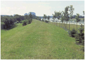
Noise from traveling motorists on major highways/interstates, airport areas, and railways can effectively be reduced using a sound barrier wall. The sound barrier wall can be formed using earth mounds or berms along the road, using high vertical walls or utilizing a combination of earth berms and walls. Since earth mounds or berms require a large area of land to construct, the tall vertical wall is more practical for limited construction areas.
Mechanically Stabilized Earth (MSE) retaining walls are used to make changes of a roadway elevation within a restricted lateral distance. Vehicular traffic may exist on either the high (fill) side of the MSE wall on the low side, or both sides. For traffic on the high side, a conventional traffic barrier might be placed on or near the top of the wall and mounted on a moment slab. For traffic on the low side, a conventional traffic barrier might be installed adjacent to the wall or the wall itself may serve as a traffic barrier.
However, typical sound barrier or MSE wall panels components are not designed to resist vehicle impacts without significant structural damage, and damage to these components would require expensive repairs.
Some of the typical designs for placing concrete barriers in front of the face of a sound barrier wall or MSE wall panels are shown in Figure 1 and Figure 2. These concrete barriers are intended to safety redirecting errant vehicles and reduce structural damage to the sound barrier wall or the MSE wall system.
Figure 2. Typical section from Juniata County, PA (2).
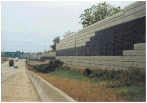
Since the mid-20th century, highway traffic sound barriers have been used extensively in the United States after noise regulations were introduced. The sound barriers are solid obstructions built between the highway and the homes along a highway to substantially reduce noise levels for people living adjacent to highways. The sound barriers can be constructed from earth, concrete, masonry, wood, metal, and other materials to effectively reduce sound transmission as shown in Figure 3. Federal Highway Administration (FHWA) has studied the benefits and effectiveness of sound barriers in 2001 (3).
  |
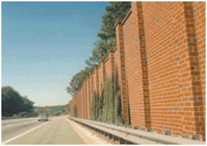 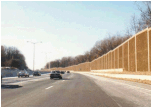 |
| Figure 3. Example of sound barriers (3). | |
MSE walls typically consist of backfill soil reinforced with either steel strips, steel bar mat, or polymeric materials. The reinforcement is attached to the retaining wall (panels) to provide stability of the MSE wall structure (Figure 2).
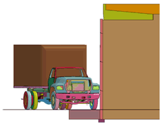
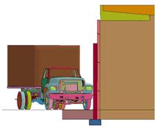
In 2010, Texas Transportation Institute (TTI) researchers reviewed, modeled, and analyzed the Pennsylvania Department of Transportation (PennDOT) crash wall design (figure 4 (4)) to determine its effectiveness to protect the MSE wall using Test Level 4 (TL-4) impact conditions of the crash testing guidelines, Manual for Assessing Safety Hardware (MASH) (5). Three finite element models were developed: (1) a typical section of an MSE wall excluding the crash wall to quantify damage to the panels impacted directly (Figure 5), (2) an MSE wall with a crash wall to quantify reduction in damage to the panels, and (3) an MSE wall with a crash wall and anchors to provide positive interaction between the wall panels and the crash wall as shown in Figure 6 (6).
Figure 4. Typical crash wall section from PennDOT drawing (4).
 |
 |
Figure 5. Set-up of MSE wall models (6).
 |
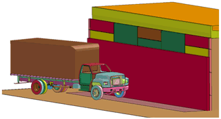 |
Figure 6. Set-up of MSE wall models with a crash wall (6).
The results of the analysis of the MSE wall impact showed that the MSE wall panels exhibited considerable damage from a direct vehicular impact as shown in Figure 7(a). This indicates that the wall panels alone cannot resist a direct impact with such severity. However, if a 0.2 m (8-inch) thick continuous crash wall is added in front of the panels, the panels exhibited less damage profile (Figure 7(b)). In this case, most of the damage was limited to the crash wall and the panels exhibited minor damage profile. Moreover, the damage is spread over smaller surface area of the crash wall than the damaged area of the MSE panels when impacted directly. Similar reduced damage profile was observed when simulating the impact on the MSE wall with a crash wall and anchors (Figure 7(c)).
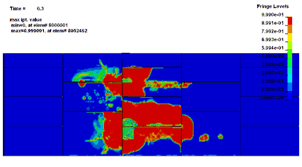 (a) Case 1: A typical MSE wall. (a) Case 1: A typical MSE wall. |
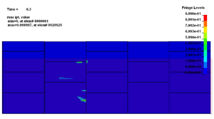 (b) Model with the crash wall (b) Model with the crash wall |
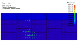 (c) Model with the crash wall and anchors (c) Model with the crash wall and anchors |
Figure 7. Comparison of damage profile on the wall panels (Impact side) (6).
The objective of this study is to model and perform a computer simulation to find the crash worthiness of offset placed single slope half size barrier wall. The single slope half size barrier is backfilled with #57 stone to absorb the energy and allow it to deflect without damaging the sound barrier walls installed along interstates or MSE walls installed at ramps. The research team will review, model, and analyze the proposed single slope half size design to determine its performance under Test Level 3 (TL-3) impact conditions of the crash testing guidelines, MASH (5).
This installation will provide continuous barrier protection along the road by using only small amount of shoulder space.
TTI will provide a report describing the engineering analysis and the numerical analysis in Tasks 1 and 2 to the pooled fund member states. A copy of all deliverables will be provided to each participating member state.
TTI will provide all the supporting information and written discussion for submitting a request to FHWA for acceptance of 51-inch single slope half size barrier for use on the National Highway System. However, since this is only a simulation effort, the FHWA may request a full-scale crash test for the system to be used on the National Highway Systems. Crash testing is not addressed in this phase but rather as subsequent research project.
Work on this project will be performed in three tasks. In Task 1, researchers will evaluate the strength of a single slope half size concrete barrier. Also, the research team will model the proposed single slope half size concrete barrier wall for protecting the sound wall or MSE walls with or without alternate offset placement. In Task 2, the research team will model and perform the computer simulation to define the appropriate lateral offset for backfill to evaluate its capacity to absorb a significant component of a TL-3-11 impact energy. In Task 3, the research team will prepare the final report to present the effort from Task 1 and Task 2.
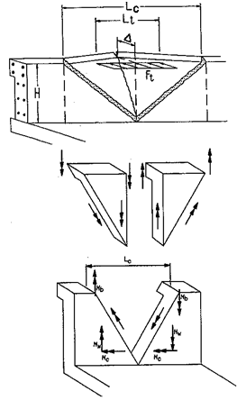
TTI researchers will perform engineering calculations on the single slope half size concrete barrier proposed by Tennessee Department of Transportation (TDOT), shown in Figure 1. The single slope half size concrete barrier will be analyzed using yield line analysis presented in Section 13 of AASHTO LRFDBridge Design Specifications (7) TL-3 requirements. Yield line theory considers the plastic strength of all the railing system components with consideration given to barrier geometry, material strengths, applied loading, and strength of the supporting bridge structure. In this case, two cases will be considered for impact within barrier segment or near end of barrier segment as shown in Figure 8.
 |
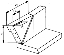 |
| (a) Impact within barrier segment | (b) Impact near end of barrier segment |
Figure 8. Yield line analysis of concrete barrier (7).
Once the strength of single slope half size concrete barrier is evaluated, the single slope half size concrete barrier in front of a sound wall or MSE wall system will be modeled using LS-DYNA (8) finite element computer program. For the first step, the model will be built without backfill offset as shown in Figure 9 provided by TDOT.
Figure 9. Single slope barrier in front of retaining wall or sound barrier (1).
The simulation task will consist of the following subtasks:
Based on previous experience of the research team, the finite element models will be constructed with suitable meshing, material models, and interface contacts to achieve balance between accuracy and computational efficiency. An example of a representative barrier model developed by TTI researchers under another project sponsored by National Cooperative Highway Research Program (NCHRP) is shown in Figure 10 (9).
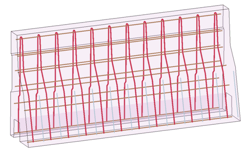
Figure 10. New Jersey barrier and reinforcing bars.
The 2007 Chevy Silverado vehicle model was developed by the National Crash Analysis Center (NCAC) (10) as shown in Figure 11. The Chevy Silverado pickup truck which meets the MASH (5) criteria of the 2270P test vehicle specification.
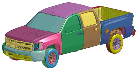
Figure 11. MASH 2270P truck model (10).
The LS-DYNA computer program will be used to determine appropriate lateral offset of backfill to absorb the energy and allow it to deform without damaging the sound barrier or the MSE walls. The proposed lateral offset is 18 inches using # 57 stone per AASHTO M43 Standard sizes of processed aggregate as shown in Figure 1. The lateral offset will be adjusted based on the computer simulation results to obtain the desirable protection.
The research team will provide a report detailing the engineering analysis, modeling and simulation work performed under Tasks 1 and 2.
| TTI Research Supervisor: Akram Abu-Odeh Texas Transportation Institute Texas A&M University System 3135 TAMU College Station, Texas 77843-3135 (979) 862-3379 [email protected] |
Pooled Fund Technical Representative: Jeff C. Jones, Director Design Division Tennessee Department of Transportation Suite 1300 James K. Polk State Office Building Nashville, TN 37243-0348 (615) 741-5789 [email protected] |
1. TDOT 51” half size single slope concrete barrier wall standard sheet, State of Tennessee Department of Transportation.
2. PennDOT BC-799m standard sheets.
3. Federal Highway Administration (2001). Keeping the Noise Down, Highway Traffic Noise Barriers, Publication No. FHWA-EP-01-004 HEPN/2-01(10M)E. http://www.fhwa.dot.gov/environment/keepdown.htm, Accessed in April 2011.
4. Standard Mechanically Stabilized Earth Retaining Walls Details and General Notes, BC-799M, Pennsylvania Department of Transportation, 2006.
5. Manual for Assessing Safety Hardware. American Association of State Highway and Transportation Officials, Washington, D.C., 2009.
6. Abu-Odeh, A., Kim, K.-M., Williams, W.F., and Buth, C.E., Crash Wall Design for Mechanically Stabilized Earth (MSE) Retaining Wall Phase I: Engineering Analysis and Simulation, TTI report No. 405160-15, Texas Transportation Institute, College Station, TX, 2010.
7. AASHTO LRFD Bridge Design Specifications, Third Edition. American Association of State Highway and Transportation Officials, Washington, D.C., 2004.
8. Hallquist, J.O., LS-DYNA: Keyword User’s Manual, Version 971, Livermore Software Technology Corporation (LSTC), Livermore, California. 2007.
9. Bligh, R.P., Briaud, J.L., Kim, K. M. and Abu-Odeh, A., Design of Roadside Barrier Systems Placed on MSE Retaining Walls, Revised final report prepared for National Cooperative Highway Research Program project 22-20, Transportation Research Board, National Research Council, performed by Texas Transportation Institute, College Station, Texas, 2009.
10. National Crash Analysis Center (NCAC), Finite Element Vehicle Models: 2007 Chevy Silverado, George Washington University, Virginia, http://www.ncac.gwu.edu/vml/models.html, Accessed in April 2011.
